Elongated pits (trenches): a sour dilemma
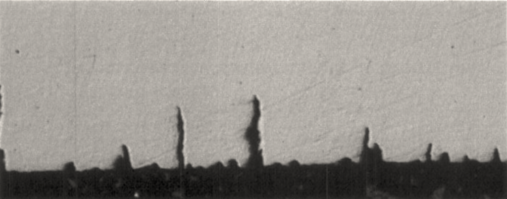
It is well known to researchers that, depending on the solution pH, temperature, total pressure, and the concentration of hydrogen sulfide (H2S) and carbon dioxide (CO2), carbon and low alloy steels often show some extent of pitting corrosion during sour service testing at the open circuit potential (EOC) (1). An intriguing feature of these pits is their large pit depth to diameter ratio resembling small nascent cracks, Figure 1. In the oil and gas industry is common to refer to such features as elongated pits or trenches as first described by Dunlop (2). In a personal communication during the 2015 Robust materialvalg i oljeindustrien congress, Stein Olsen (NACE Fellow and Statoil’s most senior corrosion expert), mentioned that in Statoil’s experience, elongated pits occur over the entire surface of the test specimen with not apparent correlation between their location and the position of maximum stress. Stein Olsen added that pitting seems more related to the surface condition than to the stress state of the sample or the harness limit (1-3).

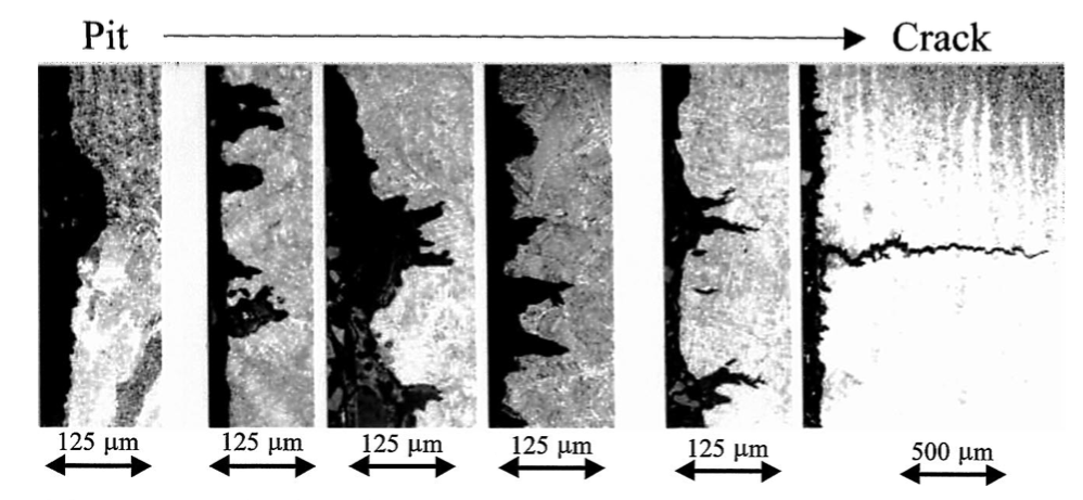
Today, many test laboratories serving the oil and gas industry use the work by Pargeter (3) to differentiate the transition from a pit to a crack. In his publication, the author proposed a flow chart summarizing the criteria for deciding whether a given feature should be labeled as a crack, a pit, or a “no crack”, Figure 2. According to Pargeter, a crack is deeper than 250μm, has a sharp tip and is perpendicular to the exposed surface in tension. The distinction between defects shallower than 250μm is less clear. In this regard, a shallow crack has to show a preference for hard microstructures and be “clearly crack-like”. There is also ambiguity in how the author differentiated between a pit and a “no crack”. A pit, according to Pargeter, is, at least, 250μm deep, but in contrast to a crack, it is not necessarily perpendicular to the exposed surface. A “no crack” is shallower than 250μm and may or may not have a preference for hard microstructures, without being “clearly crack-like”. Pargeter also includes a series of micrographs to help illustrate the gradual progression from a “no crack” to a pit and, lastly, to a crack, Figure 3.
![Figure 2. Flow chart showing a criterion for deciding on crack designation i) crack, ii) pit, and iii) no crack. Adapted from [3].](http://www.aboutcorrosion.com/wp-content/uploads/2016/01/Figure-2-1024x974.png)
Oil and gas companies and original equipment manufacturers have also established rules to differentiate between pits and cracks. Statoil’s Technical Recommendation (TR) 2023 (4), defines acceptance criteria for carbon and low alloy steels in accord with the European Federation of Corrosion (EFC) Publication No 16, Annex A. In EFC-16 approach, samples shall be free of surface and subsurface cracks (5). EFC-16 states that any [environmentally assisted]1 cracks extending more than 100μm in the through-thickness direction should be considered as causative of failure. Regarding corrosion resistant alloys (CRA), TR2023 establishes that pits with diameter less than 100μm are normally not regarded as a failure. Cracks in CRA welds that are shorter than 50μm are normally not regarded as a failure. Longer cracks need special evaluation by Statoil. The reason for differentiating between LAS and CRA is not addressed in TR2023.

Despite providing a visual aid in cataloging the type of attack observed after exposure to a sour environment, Pargeter’s criteria is not unambiguous. Additionally, the 250μm in Pargeter’s criterion or the 100μm threshold defined in EFC-16 appear arbitrary. Positively identifying the presence of cracks is crucial since all sulfide stress cracking (SSC) pass/fail criteria are based on the absence of cracks after exposure to a sour environment 2. Can we, then, postulate a quantitative definition of what constitutes a crack? Equally as important, can we determine a critical defect size above which fast brittle crack propagation will occur?
A fracture mechanics approach
Fracture mechanics (FM) principles define a threshold stress, σth, as a function of the fracture toughness of the material, KIth. Assuming that the sulfide stress cracking fracture toughness, KISSC relates to σth according to:
Where σth is in MPa, KISSC in MPa.m½, and a the defect size in m.
Thus, the critical defect size, aCrit, that will produce fast brittle SSC crack propagation can be estimated as:
The sulfide stress cracking fracture toughness is primarily a function of alloy composition and microstructure. As a rule of thumb, KISSC increases as the 0.2% offset yield strength (YS) of the material decreases (6), with fresh untempered martensite being the most deleterious microstructure (1). For quenched and tempered (QT) low alloy steels in the upper range of what is considered acceptable YS levels for Region 3 H2S exposure, i.e. between 690 and 760 MPa (100-110 ksi), a KISSC = 35 MPa.m½ appears to be an acceptable conservative value (7-8). Thus, at 760MPa, i.e. at an applied load equal to 100% YS, aCrit becomes:
Elongated pits could be differentiated from cracks based on aCrit. Assuming an approximately 2X safety margin, aCrit=300μm could be set as the deepest allowable defect, either an elongated pit, crack or “no crack.” If a defect such as an elongated pit grows deeper than aCrit, the component will suffer fast brittle failure with no plastic deformation when the total tensile stress exceeds σth.
FM principles provide a quantitative and unambiguous methodology to define pass/fail thresholds, facilitating the usually challenging interpretation of SSC test results. This approach has also been proposed by Staehle and Gorman, who used the stress corrosion cracking threshold, KISCC, to determine a critical stress for stress corrosion crack propagation (9).
The second part of this series discusses whether cracks always nucleate from pits.
Bibliography
- Kappes, M., M. Iannuzzi, R.B. Rebak, and R.M. Carranza, Corrosion Reviews 32 (2014): pp. 101–128.
- Dunlop, A. K. (1978). Stress corrosion cracking of low strength, low alloy nickel steels in sulfide environments. Corrosion, 34(3), 88-96.
- Pargeter, J., Paper No 00143, “The Effect of Low H2S Concentrations on Welded Steels,” in Corrosion/00 (Houston, TX: NACE International, 2000).
- TR2023: “H2S Cracking Resistant Materials,” 4th Ed. (Fornebu, Norway: Statoil, 2012).
- “Procedures and Guidelines for Sulphide Stress Cracking Testing,” in EFC Publication No 16: “Guidelines on Materials Requirements for Carbon and Low Alloy Steels for H 2 S-Containing Environments in Oil and Gas Production”, 3rd Ed. (Leeds, U.K.: Maney Publishing, 2009), pp.23–36. Buy at Amazon.
- Oakwood, H.G., “Corrosion of Wrought Low-Alloy Steels,” in ASM Handbook, Volume 13B, ed. S.D. Cramer, 1st ed. (Metals Park, OH, 2005), pp.11–27. Buy at Amazon.
- Kondo, K., H. Amaya, H. Takabe, M. Ueda, J. Nakamura, and M. Tanida, Paper No C2014–3896, “Effect of Crack Starter on KISSC and Compliance for DCB Test,” in Corrosion/14 (Houston, TX: NACE International, 2014).
- Saha, S.K., and E.J. Hilinski, Paper No C2012–2079, “Study of C110 Critical Stress Intensity Factor (KISSC) In Various Weak H2S Solutions,” in Corrosion/13 (NACE International, 2013).
- Staehle, R.W., and J.A. Gorman, Corrosion 60, (2004):pp5-63.
